SMART CARD
1. INTRODUCTION:
A smart card, chip card, or integrated circuit card (ICC), is any pocket-sized card with embedded integrated circuits which can process data. This implies that it can receive input which is processed — by way of the ICC applications — and delivered as an output.
There are two broad categories of ICCs.
a)Memory cards
b)Microprocessor cards
a)Memory cards : It contain only non-volatile memory storage components, and perhaps some specific security logic.
The card is made of plastic, generally PVC, but sometimes ABS. The card may embed a hologram to avoidcounterfeiting. Using smart cards is also a form of strong security authentication for single sign-on within large companies and organizations.
A "smart card" is also characterized as follows:
Dimensions are normally credit card size. The ID-1 of ISO/IEC 7810 standard defines them as 85.60 × 53.98 mm. Another popular size is ID-000 which is 25 × 15 mm (commonly used in SIM cards). Both are 0.76 mm thick.
Contains a security system with tamper-resistant properties (e.g. a secure cryptoprocessor, secure file system, human-readable features) and is capable of providing security services (e.g. confidentiality of information in the memory).
Card data is transferred to the central administration system through card reading devices, such as ticket readers, ATMs etc.
2.History of smart card is as follows:
The automated chip card was invented by German rocket scientist Helmut Gröttrup and his colleague Jürgen Dethloff in 1968; the patent was finally approved in 1982. The first mass use of the cards was for payment in French pay phones, starting in 1983
The second use was with the integration of microchips into all French debit cards (Carte Bleue) completed in 1992. When paying in France with a Carte Bleue, one inserts the card into the merchant's POS terminal, then types the PIN, before the transaction is accepted. Only very limited transactions (such as paying small autoroute tolls) are accepted without PIN.
The major boom in smart card use came in the 1990s, with the introduction of the smart-card-based SIM used in GSM mobile phone equipment in Europe. With the ubiquity of mobile phones in Europe, smart cards have become very common.
The international payment brands MasterCard, Visa, and Europay agreed in 1993 to work together to develop the specifications for the use of smart cards in payment cards used as either a debit or a credit card. The first version of the EMV system was released in 1994. In 1998 a stable release of the specifications was available. EMVco, the company responsible for the long-term maintenance of the system, upgraded the specification in 2000 and most recently in 2004. The goal of EMVco is to assure the various financial institutions and retailers that the specifications retain backward compatibility with the 1998 version.
3. BENEFITS:
Ø Smart cards can be used for identification, authentication, and data storage.
Ø Smart card can provide strong authentication for single sign-on or enterprise single sign-on to computers, laptops, data with encryption,enterprise resource planning platforms such as SAP, etc.
4. TYPES OF SMART CARD:
a) contact smart card
b) contact less smart card
4.1 Contact smart card
Contact smart cards have a contact area, comprising several gold-plated contact pads, that is about 1 cm square. When inserted into a reader, the chip makes contact with electrical connectors that can read information from the chip and write information back.[3]
§ the physical shape
§ the positions and shapes of the electrical connectors
§ the electrical characteristics
§ the communications protocols, that includes the format of the commands sent to the card and the responses returned by the card.
§ robustness of the card
§ the functionality
The cards do not contain batteries; energy is supplied by the card reader.
Electrical signals description
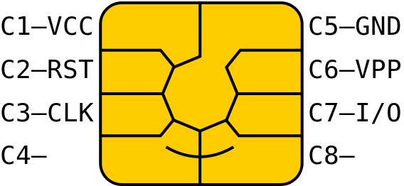
VCC : Power supply input
RST : Either used itself (reset signal supplied from the interface device) or in combination with an internal reset control circuit (optional use by the card). If internal reset is implemented, the voltage supply on Vcc is mandatory.
CLK : Clocking or timing signal (optional use by the card).
VPP : Programming voltage input (deprecated / optional use by the card).
I/O : Input or Output for serial data to the integrated circuit inside the card.
NOTE - The use of the two remaining contacts will be defined in the appropriate application standards.
Reader
Contact smart card readers are used as a communications medium between the smart card and a host, e.g. a computer, a point of sale terminal, or a mobile telephone.

4.2 Contactless smart card:

A second type is the contactless smart card, in which the chip communicates with the card reader through RFID induction technology (at data rates of 106 to 848 kbit/s). These cards require only close proximity to an antenna to complete transaction. They are often used when transactions must be processed quickly or hands-free, such as on mass transit systems, where smart cards can be used without even removing them from a wallet.
The standard for contactless smart card communications is ISO/IEC 14443. It defines two types of contactless cards ("A" and "B"), allows for communications at distances up to 10 cm. There had been proposals for ISO/IEC 14443 types C, D, E, F and G that have been rejected by the International Organization for Standardization. An alternative standard for contactless smart cards is ISO 15693, which allows communications at distances up to 50 cm.
A related contactless technology is RFID (radio frequency identification). In certain cases, it can be used for applications similar to those of contactless smart cards, such as for electronic toll collection. RFID devices usually do not include writeable memory or microcontroller processing capability as contactless smart cards often do.
There are dual-interface cards that implement contactless and contact interfaces on a single card with some shared storage and processing. An example is Porto's multi-application transport card, called Andante, that uses a chip in contact and contactless (ISO/IEC 14443 Type B).
Like smart cards with contacts, contactless cards do not have a battery. Instead, they use a built-in inductor to capture some of the incident radio-frequency interrogation signal, rectify it, and use it to power the card's electronics.
Cryptographic smart cards
Cryptographic smart cards are often used for single sign-on. Most advanced smart cards include specialized cryptographic hardware that uses algorithms such as RSA and DSA. Today's cryptographic smart cards are also able to generate key pairs on board, to avoid the risk of having more than one copy of the key (since by design there usually isn't a way to extract private keys from a smart card).
The most common way to access cryptographic smart card functions on a computer is to use aPKCS#11 library provided by the vendor. On Microsoft Windows platforms the CSP API is also adopted.
The most widely used cryptographic algorithms in smart cards (excluding the GSM so-called "crypto algorithm") are Triple DES and RSA. The key set is usually loaded (DES) or generated (RSA) on the card at the personalization stage.
5. TECHNOLOGY:
5.1 Microprocessor Logic
Photo courtesy Intel Corporation 
Intel Pentium 4 processor
|
To understand how a microprocessor works, it is helpful to look inside and learn about the logic used to create one. In the process you can also learn about assembly language -- the native language of a microprocessor -- and many of the things that engineers can do to boost the speed of a processor.
A microprocessor executes a collection of machine instructions that tell the processor what to do. Based on the instructions, a microprocessor does three basic things:
· Using its ALU (Arithmetic/Logic Unit), a microprocessor can perform mathematical operations like addition, subtraction, multiplication and division. Modern microprocessors contain complete floating point processors that can perform extremely sophisticated operations on large floating point numbers.
· A microprocessor can make decisions and jump to a new set of instructions based on those decisions.
There may be very sophisticated things that a microprocessor does, but those are its three basic activities. The following diagram shows an extremely simple microprocessor capable of doing those three things:
This is about as simple as a microprocessor gets. This microprocessor has:
· An address bus (that may be 8, 16 or 32 bits wide) that sends an address to memory
· A data bus (that may be 8, 16 or 32 bits wide) that can send data to memory or receive data from memory
· An RD (read) and WR (write) line to tell the memory whether it wants to set or get the addressed location
· A clock line that lets a clock pulse sequence the processor
· A reset line that resets the program counter to zero (or whatever) and restarts execution
Let's assume that both the address and data buses are 8 bits wide in this example.
Here are the components of this simple microprocessor:
· Registers A, B and C are simply latches made out of flip-flops. (See the section on "edge-triggered latches" in How Boolean Logic Works for details.)
· The address latch is just like registers A, B and C.
· The program counter is a latch with the extra ability to increment by 1 when told to do so, and also to reset to zero when told to do so.
· The ALU could be as simple as an 8-bit adder (see the section on adders in How Boolean Logic Works for details), or it might be able to add, subtract, multiply and divide 8-bit values. Let's assume the latter here.
· The test register is a special latch that can hold values from comparisons performed in the ALU. An ALU can normally compare two numbers and determine if they are equal, if one is greater than the other, etc. The test register can also normally hold a carry bit from the last stage of the adder. It stores these values in flip-flops and then the instruction decoder can use the values to make decisions.
· There are six boxes marked "3-State" in the diagram. These are tri-state buffers. A tri-state buffer can pass a 1, a 0 or it can essentially disconnect its output (imagine a switch that totally disconnects the output line from the wire that the output is heading toward). A tri-state buffer allows multiple outputs to connect to a wire, but only one of them to actually drive a 1 or a 0 onto the line.
The instruction register and instruction decoder are responsible for controlling all of the other components. Although they are not shown in this diagram, there would be control lines from the instruction decoder that would:
· Tell the A register to latch the value currently on the data bus
· Tell the B register to latch the value currently on the data bus
· Tell the C register to latch the value currently output by the ALU
· Tell the program counter register to latch the value currently on the data bus
· Tell the address register to latch the value currently on the data bus
· Tell the instruction register to latch the value currently on the data bus
· Tell the program counter to increment
· Tell the program counter to reset to zero
· Activate any of the six tri-state buffers (six separate lines)
· Tell the ALU what operation to perform
· Tell the test register to latch the ALU's test bits
· Activate the RD line
· Activate the WR line
Coming into the instruction decoder are the bits from the test register and the clock line, as well as the bits from the instruction register.
5.2 RFID:
Long checkout lines at the grocery store are one of the biggest complaints about the shopping experience. Soon, these lines could disappear when the ubiquitous Universal Product Code (UPC) bar code is replaced by smart labels, also called radio frequency identification (RFID) tags. RFID tags are intelligent bar codes that can talk to a networked system to track every product that you put in your shopping cart.
Imagine going to the grocery store, filling up your cart and walking right out the door. No longer will you have to wait as someone rings up each item in your cart one at a time. Instead, these RFID tags will communicate with an electronic reader that will detect every item in the cart and ring each up almost instantly. The reader will be connected to a large network that will send information on your products to the retailer and product manufacturers. Your bank will then be notified and the amount of the bill will be deducted from your account. No lines, no waiting.
RFID tags, a technology once limited to tracking cattle, are tracking consumer products worldwide. Many manufacturers use the tags to track the location of each product they make from the time it's made until it's pulled off the shelf and tossed in a shopping cart.
Outside the realm of retail merchandise, RFID tags are tracking vehicles, airline passengers, Alzheimer's patients and pets. Soon, they may even track your preference for chunky or creamy peanut butter. Some critics say RFID technology is becoming too much a part of our lives -- that is, if we're even aware of all the parts of our lives that it affects.
5.3 DESalgorithm
The Data Encryption Standard (DES) algorithm, adopted by the U.S.
government in 1977, is a block cipher that transforms 64-bit data
blocks under a 56-bit secret key, by means of permutation and
substitution. It is officially described in FIPS PUB 46. The DES
algorithm is widely used and is still considered reasonably secure.
This is a tutorial designed to be clear and compact, and to provide a
newcomer to the DES with all the necessary information to implement it
himself, without having to track down printed works or wade through C
source code. I welcome any comments.
Matthew Fischer <mfischer@heinous.music.uiowa.edu>
Here's how to do it, step by step:
1 Process the key.
1.1 Get a 64-bit key from the user. (Every 8th bit (the least
significant bit of each byte) is considered a parity bit. For a key to
have correct parity, each byte should contain an odd number of "1"
bits.) This key can be entered directly, or it can be the result of
hashing something else. There is no standard hashing algorithm for this
purpose.
1.2 Calculate the key schedule.
1.2.1 Perform the following permutation on the 64-bit key. (The
parity bits are discarded, reducing the key to 56 bits. Bit 1 (the most
significant bit) of the permuted block is bit 57 of the original key,
bit 2 is bit 49, and so on with bit 56 being bit 4 of the original key.)
Permuted Choice 1 (PC-1)
57 49 41 33 25 17 9
1 58 50 42 34 26 18
10 2 59 51 43 35 27
19 11 3 60 52 44 36
63 55 47 39 31 23 15
7 62 54 46 38 30 22
14 6 61 53 45 37 29
21 13 5 28 20 12 4
1.2.2 Split the permuted key into two halves. The first 28 bits are
called C[0] and the last 28 bits are called D[0].
1.2.3 Calculate the 16 subkeys. Start with i = 1.
1.2.3.1 Perform one or two circular left shifts on both C[i-1] and
D[i-1] to get C[i] and D[i], respectively. The number of shifts per
iteration are given in the table below.
Iteration # 1 2 3 4 5 6 7 8 9 10 11 12 13 14 15 16
Left Shifts 1 1 2 2 2 2 2 2 1 2 2 2 2 2 2 1
1.2.3.2 Permute the concatenation C[i]D[i] as indicated below. This
will yield K[i], which is 48 bits long.
Permuted Choice 2 (PC-2)
14 17 11 24 1 5
3 28 15 6 21 10
23 19 12 4 26 8
16 7 27 20 13 2
41 52 31 37 47 55
30 40 51 45 33 48
44 49 39 56 34 53
46 42 50 36 29 32
1.2.3.3 Loop back to 1.2.3.1 until K[16] has been calculated.
2 Process a 64-bit data block.
2.1 Get a 64-bit data block. If the block is shorter than 64 bits, it
should be padded as appropriate for the application.
2.2 Perform the following permutation on the data block.
Initial Permutation (IP)
58 50 42 34 26 18 10 2
60 52 44 36 28 20 12 4
62 54 46 38 30 22 14 6
64 56 48 40 32 24 16 8
57 49 41 33 25 17 9 1
59 51 43 35 27 19 11 3
61 53 45 37 29 21 13 5
63 55 47 39 31 23 15 7
2.3 Split the block into two halves. The first 32 bits are called
L[0], and the last 32 bits are called R[0].
2.4 Apply the 16 subkeys to the data block. Start with i = 1.
2.4.1 Expand the 32-bit R[i-1] into 48 bits according to the
bit-selection function below.
Expansion (E)
32 1 2 3 4 5
4 5 6 7 8 9
8 9 10 11 12 13
12 13 14 15 16 17
16 17 18 19 20 21
20 21 22 23 24 25
24 25 26 27 28 29
28 29 30 31 32 1
2.4.2 Exclusive-or E(R[i-1]) with K[i].
2.4.3 Break E(R[i-1]) xor K[i] into eight 6-bit blocks. Bits 1-6 are
B[1], bits 7-12 are B[2], and so on with bits 43-48 being B[8].
2.4.4 Substitute the values found in the S-boxes for all B[j]. Start
with j = 1. All values in the S-boxes should be considered 4 bits wide.
2.4.4.1 Take the 1st and 6th bits of B[j] together as a 2-bit value
(call it m) indicating the row in S[j] to look in for the substitution.
2.4.4.2 Take the 2nd through 5th bits of B[j] together as a 4-bit
value (call it n) indicating the column in S[j] to find the substitution.
2.4.4.3 Replace B[j] with S[j][m][n].
Substitution Box 1 (S[1])
14 4 13 1 2 15 11 8 3 10 6 12 5 9 0 7
0 15 7 4 14 2 13 1 10 6 12 11 9 5 3 8
4 1 14 8 13 6 2 11 15 12 9 7 3 10 5 0
15 12 8 2 4 9 1 7 5 11 3 14 10 0 6 13
S[2]
15 1 8 14 6 11 3 4 9 7 2 13 12 0 5 10
3 13 4 7 15 2 8 14 12 0 1 10 6 9 11 5
0 14 7 11 10 4 13 1 5 8 12 6 9 3 2 15
13 8 10 1 3 15 4 2 11 6 7 12 0 5 14 9
S[3]
10 0 9 14 6 3 15 5 1 13 12 7 11 4 2 8
13 7 0 9 3 4 6 10 2 8 5 14 12 11 15 1
13 6 4 9 8 15 3 0 11 1 2 12 5 10 14 7
1 10 13 0 6 9 8 7 4 15 14 3 11 5 2 12
S[4]
7 13 14 3 0 6 9 10 1 2 8 5 11 12 4 15
13 8 11 5 6 15 0 3 4 7 2 12 1 10 14 9
10 6 9 0 12 11 7 13 15 1 3 14 5 2 8 4
3 15 0 6 10 1 13 8 9 4 5 11 12 7 2 14
S[5]
2 12 4 1 7 10 11 6 8 5 3 15 13 0 14 9
14 11 2 12 4 7 13 1 5 0 15 10 3 9 8 6
4 2 1 11 10 13 7 8 15 9 12 5 6 3 0 14
11 8 12 7 1 14 2 13 6 15 0 9 10 4 5 3
S[6]
12 1 10 15 9 2 6 8 0 13 3 4 14 7 5 11
10 15 4 2 7 12 9 5 6 1 13 14 0 11 3 8
9 14 15 5 2 8 12 3 7 0 4 10 1 13 11 6
4 3 2 12 9 5 15 10 11 14 1 7 6 0 8 13
S[7]
4 11 2 14 15 0 8 13 3 12 9 7 5 10 6 1
13 0 11 7 4 9 1 10 14 3 5 12 2 15 8 6
1 4 11 13 12 3 7 14 10 15 6 8 0 5 9 2
6 11 13 8 1 4 10 7 9 5 0 15 14 2 3 12
S[8]
13 2 8 4 6 15 11 1 10 9 3 14 5 0 12 7
1 15 13 8 10 3 7 4 12 5 6 11 0 14 9 2
7 11 4 1 9 12 14 2 0 6 10 13 15 3 5 8
2 1 14 7 4 10 8 13 15 12 9 0 3 5 6 11
2.4.4.4 Loop back to 2.4.4.1 until all 8 blocks have been replaced.
2.4.5 Permute the concatenation of B[1] through B[8] as indicated below.
Permutation P
16 7 20 21
29 12 28 17
1 15 23 26
5 18 31 10
2 8 24 14
32 27 3 9
19 13 30 6
22 11 4 25
2.4.6 Exclusive-or the resulting value with L[i-1]. Thus, all together,
your R[i] = L[i-1] xor P(S[1](B[1])...S[8](B[8])), where B[j] is a 6-bit
block of E(R[i-1]) xor K[i]. (The function for R[i] is more concisely
written as, R[i] = L[i-1] xor f(R[i-1], K[i]).)
2.4.7 L[i] = R[i-1].
2.4.8 Loop back to 2.4.1 until K[16] has been applied.
2.5 Perform the following permutation on the block R[16]L[16]. (Note
that block R precedes block L this time.)
Final Permutation (IP**-1)
40 8 48 16 56 24 64 32
39 7 47 15 55 23 63 31
38 6 46 14 54 22 62 30
37 5 45 13 53 21 61 29
36 4 44 12 52 20 60 28
35 3 43 11 51 19 59 27
34 2 42 10 50 18 58 26
33 1 41 9 49 17 57 25
This has been a description of how to use the DES algorithm to encrypt
one 64-bit block. To decrypt, use the same process, but just use the keys
K[i] in reverse order. That is, instead of applying K[1] for the first
iteration, apply K[16], and then K[15] for the second, on down to K[1].
Summaries:
Key schedule:
C[0]D[0] = PC1(key)
for 1 <= i <= 16
C[i] = LS[i](C[i-1])
D[i] = LS[i](D[i-1])
K[i] = PC2(C[i]D[i])
Encipherment:
L[0]R[0] = IP(plain block)
for 1 <= i <= 16
L[i] = R[i-1]
R[i] = L[i-1] xor f(R[i-1], K[i])
cipher block = FP(R[16]L[16])
Decipherment:
R[16]L[16] = IP(cipher block)
for 1 <= i <= 16
R[i-1] = L[i]
L[i-1] = R[i] xor f(L[i], K[i])
plain block = FP(L[0]R[0])
To encrypt or decrypt more than 64 bits there are four official modes
(defined in FIPS PUB 81). One is to go through the above-described
process for each block in succession. This is called Electronic Codebook
(ECB) mode. A stronger method is to exclusive-or each plaintext block
with the preceding ciphertext block prior to encryption. (The first
block is exclusive-or'ed with a secret 64-bit initialization vector
(IV). This IV is generally a random value that is kept with the key.)
This is called Cipher Block Chaining (CBC) mode. The other two modes
are Output Feedback (OFB) and Cipher Feedback (CFB).
When it comes to padding the data block, there are several options. One
is to simply append zeros. Two suggested by FIPS PUB 81 are, if the
data is binary data, fill up the block with bits that are the opposite
of the last bit of data, or, if the data is ASCII data, fill up the
block with random characters and put the ASCII character for the number
of pad characters in the last byte of the block.
The DES algorithm can also be used to calculate cryptographic checksums
up to 64 bits long (see FIPS PUB 113). If the number of data bits to be
checksummed is not a multiple of 64, the last data block should be
padded with zeros. If the data is ASCII data, the most significant bit
of each byte should be set to 0. The data is then encrypted in CBC mode
with IV = 0. The most significant n bits (where 16 <= n <= 64, and n is
a multiple of 8) of the final ciphertext block are an n-bit checksum.
5.4 RSA ALGORITHM:
The RSA algorithm was designed by Rivest, Shamir and Adleman in 1978. It is a public key
cryptosystem that can also be used for signing messages. The algorithm makes use of 3
mathematical properties (as described in [RivSA78] and [Til99]):
1. Exponentiation modulo a composite number n, i.e. computing c from c = me (mod n) for
given m and e, is a relatively simple operation.
2. The opposite problem of taking roots modulo a large, composite number n, i.e. computing
m from c = me (mod n) for given c and e, is, in general, believed to be intractable.
3. If the prime factorization of n is known, the problem of taking roots modulo n is feasible.
Property 1 makes encoding and decoding possible, property 2 ensures that decoding is not
possible without the correct key and property 3 is needed in the setup of the algorithm .
Algorithm Setup
In order to use RSA some pre-calculations have to be made. RSA is based on calculating
powers of large integers modulo a large composite number. These numbers have to be
generated before the system can be used. We want to create a public key eB and a
corresponding private key dB. These keys are constructed as follows:
- two large primes pB and qB are chosen
- the modulus nB is the product of pB and qB
- public key eB is a randomly chosen number such that GCD( eB, (pB-1) * (qB-1) ) = 1
- the private key dB is the multiplicative inverse of eB modulo (pB-1) * (qB-1)
The public key eB and the modulus nB are made public while the rest of the numbers are kept
secret. We have used 512 bit numbers for each which is a commonly used length for keys in
the RSA algorithm.
Encryption and Decryption
After this setup (which can be done easily using, for example, Mathematica as shown above) encryption of plain text message m using public key eB to cipher text c is
accomplished by calculating: c = meB mod n.
The message m can be recovered from c by calculating m = cdB mod n.
6. FABRICATION OF SMART CARDS
The manufacture of a smart card involves a large number of
processes of which the embedding of the chip into the plastic card is key in
achieving an overall quality product. This latter process is usually referred to
as card fabrication.
6.1 Chip specification
There are a number of factors to be decided in the specification of the
integrated circuit for the smart card. The key parameters for the chip
specification are as follows:-
a. Microcontroller type (e.g 6805,8051)
b. Mask ROM size
c. RAM size.3
d. Non volatile memory type (e.g EPROM, EEPROM)
e. Non volatile memory size
f. Clock speed (external, and optionally internal)
g. Electrical parameters (voltage and current)
h. Communications parameters (asynchronous, synchronous, byte, block)
i. Reset mechanism
j. Sleep mode (low current standby operation)
k. Co-processor (e.g for public key cryptography)
6.2 Card specification
The specification of a card involves parameters that are common to
many existing applications using the ISO ID-1 card. The following list
defines the main parameters that should be defined,
21
a. Card dimensions
b. Chip location (contact card)
c. Card material (e.g PVC, ABS)
d. Printing requirements
e. Magnetic stripe (optional)
f. Signature strip (optional)
g. Hologram or photo (optional)
h. Embossing (optional)
i. Environmental parameters
The choice of card material effects the environmental properties of
the finished product. PVC was traditionally used in the manufacture of cards
and enabled a higher printing resolution. Such cards are laminated as three
layers with transparent overlays on the front and back. More recently ABS
has been used which allows the card to be produced by an injection
moulding process. It is even proposed that the chip micromodule could be
inserted in one step as part of the moulding process. Temperature stability is
clearly important for some applications and ETSI are particulary concerned
here, such that their higher temperature requirement will need the use of
polycarbonate materials.
6.3 Mask ROM Specification
The mask ROM contains the operating system of the smart card. It
is largely concerned with the management of data files but it may optionally
involve additional features such as cryptographic algorithms (e.g DES). In
some ways this is still a relatively immature part of the smart card standards
since the early applications used the smart card largely as a data store with
some simple security features such as PIN checking. The relevant part of the
ISO standard is 7816-4 (commands).There is a school of thought that
envisages substantial changes in this area to account for the needs of multiapplication
cards where it is essential to provide the necessary security
segregation. The developed code is given to the supplier who incorporates
this data as part of the chip manufacturing process.
6.4 Application Software Specification
This part of the card development process is clearly specific to the
particular application. The application code could be designed as part of the
mask ROM code but the more modern approach is to design the application
software to operate from the PROM non volatile memory. This allows a far
more flexible approach since the application can be loaded into the chip after
manufacture. More over by the use of EEPROM it is possible to change this
code in an development environment. The manufacturer of a chip with the
users ROM code takes on average three months. Application code can be
loaded into the PROM memory in minutes with no further reference to the
chip manufacturer.
6.5 Chip Fabrication
The first part of the process is to manufacture a substrate which contains
the chip. This is often called a COB (Chip On Board) and consists of a glass
epoxy connector board on which the chip is bonded to the connectors. There are
three technologies available for this process, wire bonding, flip chip processing
and tape automated bonding (TAB). In each case the semiconductor wafer
manufactured by the semiconductor supplier is diced into individual chips . This
may be done by scribing with a diamond tipped point and then pressure rolling
the wafers so that it fractures along the scribe lines. More commonly the die are
separated from the wafer by the use of a diamond saw. A mylar sheet is stuck to
the back of the wafer so that following separation the dice remain attached to the
mylar film. Wire bonding is the most commonly used technique in the
manufacture of smart cards. Here a 25uM gold or aluminium wire is bonded to
the pads on the chip using ultrasonic or thermo compression bonding.
Thermo compression bonding requires the substrate to be maintained at
between 150C and 200C. The temperature at the bonding interface can reach
350C. To alleviate these problems thermo sonic bonding is often used which
is a combination of the two processes but which operate at lower
temperatures. The die mounting and wire bonding processes involve a large
number of operations and are therefore quite expensive. However in the
semiconductor industry generally two other techniques are used, the flip
chip process and tape automated bonding. In both cases gold bumps are
formed on the die. In flip chip processing the dice are placed face down on
the substrate and bonding is effected by solder reflow. With tape automated
bonding the dice are attached by thermocompression to copper leads
supported on a flexible tape similar to a 35mm film. The finished substrate is
hermetically sealed with an inert material such as epoxy resin. The complete
micromodule is then glued into the card which contains the appropriately
sized hole. The fabrication of a contactless card is somewhat different since
it always involves a laminated card. The ICs and their interconnections as
well as the aerial circuits are prepared on a flexible polyimide substrate.
6.6 Application load
Assuming the application is to be placed in the PROM memory of
the IC then the next stage in the process is to load the code into the memory.
This is accomplished by using the basic commands contained in the
operating system in the mask ROM. These commands allow the reading and
writing of the PROM memory.
6.7 Card Personalisation
The card is personalized to the particular user by loading data into
files in the PROM memory in the same way that the application code is
loaded into memory. At this stage the security keys will probably be loaded
into the PROM memory but as mentioned previously we will explore this in
more detail later.
6.8 Application Activation
The final operation in the manufacturing process is to enable the
application for operation. This will involve the setting of flags in the PROM
memory that will inhibit any further changes to be made to the PROM
memory except under direct control of the application. Again this is an
integral part of the overall security process.
7. APPLICATIONS:
Computer security
The Mozilla Firefox web browser can use smart cards to store certificates for use in secure web browsing.Some disk encryption systems, such as FreeOTFE, TrueCrypt and Microsoft Windows 7 BitLocker, can use smart cards to securely hold encryption keys, and also to add another layer of encryption to critical parts of the secured disk.
Smart cards support functionality has been added to Windows Live Passports
Financial
The applications of smart cards include their use as credit or ATM cards, in a fuel card, SIMs for mobile phones, authorization cards for pay television, pre-pay utilities in household, high-security identification and access-control cards, and public transport and public phone payment cards.
Smart cards may also be used as electronic wallets. The smart card chip can be loaded with funds which can be spent in parking meters and vending machines or at various merchants. Cryptographic protocols protect the exchange of money between the smart card and the accepting machine. There is no connection to the issuing bank necessary, so the holder of the card can use it regardless of him being the owner. Examples are Proton, Geldkarte, Chipknip and Mon€o. The German Geldkarte is also used to validate customer age at vending machines for cigarettes.
Health care (Medical)
Smart health cards can improve the security and privacy of patient information, provide the secure carrier for portable medical records, reduce health care fraud, support new processes for portable medical records, provide secure access to emergency medical information, enable compliance with government initiatives and mandates, and provide the platform to implement other applications as needed by the health care organization.
Identification
A quickly growing application is in digital identification cards. In this application, the cards are used for authentication of identity. The most common example is in conjunction with a PKI. The smart card will store an encrypted digital certificate issued from the PKI along with any other relevant or needed information about the card holder. Examples include the U.S. Department of Defense (DoD) Common Access Card(CAC), and the use of various smart cards by many governments as identification cards for their citizens. When combined with biometrics, smart cards can provide two- or three-factor authentication. Smart cards are not always a privacy-enhancing technology, for the subject carries possibly incriminating information about him all the time. By employing contactless smart cards, that can be read without having to remove the card from the wallet or even the garment it is in, one can add even more authentication value to the human carrier of the cards.
The first smart card driver's license system in the world was issued in 1995 in Mendoza, a province of Argentina. Mendoza has a high level of road accidents, driving offenses, and a poor record of recovering outstanding fines. The smart licenses keep an up-to-date record of driving offenses and unpaid fines. They also store personal information, license type and number, and a photograph of the holder. Emergency medical information like blood type, allergies, and biometrics (fingerprints) can be stored on the chip if the cardholder wishes. The Argentina government anticipates that this new system will help to recover more than $10 million per year in fines.
Gujarat was the first state in India to introduce the smart card license system in 1999. To date the Gujarat Government has issued 5 million smart card driving licenses to its people.[citation needed] This card is basically a plastic card with integrated circuit, capable of storing and verifying information according to its programming.
"a national ID card, protected by a 1,024-bit key code, is impossible to break without a supercomputer working away for a hundred years"
By the start of 2009 the entire population of Spain and Belgium will have an eID card, that is issued by the Spanish and Belgian Governments and that is used to identify an individual. These cards contain 2 certificates: one for authentication and one for signature. This signature is legally adopted. More and more services in these countries are using the eID card as an authorization token.
Other
Smart cards are widely used to protect digital television streams. See television encryption for an overview, and VideoGuard is a specific example of how smart card security worked (and was cracked).
The Malaysian government uses smart card technology in identity cards carried by all citizens and resident non-citizens. The personal information inside the smart card (called MYKAD) can be read using special APDU commands.MYKAD SDK
8. SECURITY:
Smart cards have been advertised as suitable for personal identification tasks, because they are engineered to be tamper resistant. The embedded chip of a smart card usually implements some cryptographic algorithm. There are, however, several methods of recovering some of the algorithm's internal state.
Differential power analysis
Differential power analysis involves measuring the precise time and electrical current required for certain encryption or decryption operations. This is most often used against public key algorithms such as RSA in order to deduce the on-chip private key, although some implementations of symmetric ciphers can be vulnerable to timing or power attacks as well.
Physical disassembly
Smart cards can be physically disassembled by using acid, abrasives, or some other technique to obtain direct, unrestricted access to the on-board microprocessor. Although such techniques obviously involve a fairly high risk of permanent damage to the chip, they permit much more detailed information (e.g. photomicrographs of encryption hardware) to be extracted.
CONCLUSION
Smart card is an excellent technology to secure storage and
authentication. If an organization can deploy this technology selecting the
right type of solutions which is cross platform compatible and supports the
standards required, it would be economical as well as secure. This
technology has to be standardized and used in various applications in an
organization not just for physical access or information access. Various
developments are happening in the smart card industry with respect to
higher memory capacities and stronger encryption algorithms which could
provide us with much tougher security. But we need to understand that we
will achieve better security only if we have users educated to use these
technology with at most care. A smart world is the future.